Tuning magnetoresistance by mastered effects: chirality and trapped fields
Project Director: Dr. Anda-Elena STANCIU
Project Acronym: MR_Helix
Final registration code: PN-III-P1-1.1-PD-2019-1141
Project leader: Dr. Anda-Elena Stanciu
Mentor: Dr. Ioan Adrian Crisan
Project Category: National Projects
Start Date: 09/01/2020
End Date: 10/31/2022
The scope of the project is to tune magnetoresistive (MR) properties in soft magnetic
systems by stress anisotropy, chirality effects and, subsequently, by an indirect coupling between the
electrical resistance and the spin structure, via trapped field magnets in superconductors.
Motivation. Modern research efforts in perfecting MR-based technologies are directed towards
new materials with large spin polarization, controllable magnetization and magnetic anisotropy. The
magnetic anisotropy is a feature that confers different magnetic properties at different orientations of an
external applied magnetic field. Therefore, the key parameters to control the desired magnetic properties
for technological applications are related to components of the magnetic anisotropy: crystallinity, shape
and stress. Methods to optimize and control the magnetic anisotropy and magnetic properties can be
established via intrinsic (elemental composition, magnetostriction) and extrinsic (dimensionality,
disposal, chirality) effects. Taking into account the limited possibilities to adjust MR by elemental
composition, concentration, morpho-structural aspects and the fact that they have been already explored, extrinsic effects should be also approached.
The first objective is to tune the MR by rolling-up the ribbons in helices and to study the influence
of the electrical magneto-chiral effect and of the stress anisotropy on the magneto-resistive properties of
the ribbons. When electrical conductors are chiral, the resistance strongly depend on the current through,
on the chirality and/or on the external magnetic field, all these parameters defining the Electrical
Magneto-Chiral Anisotropy (EMCA). A current carried by a chiral conductor will generate a
magnetic field along the helicity, equivalent to a magnetization which direction depends on the direction
of the current and the handedness of the conductor. When an external magnetic field is applied, it couples
to the internal magnetization and affects the MR by its direction. Therefore, EMCA anisotropy can be
used to tune electromagnetic properties.
The second objective is to induce magnetic anisotropy in magnetic (ferrimagnetic) thin films and
curled ribbons using a magnetized superconductor acting as a trapped field magnet. In the case of thin films, the magnetic (ferrimagnetic) film will be deposited over a superconducting substrate with an intermediary insulating layer, whereas in the case of ribbons, they will be curled over a superconducting
wire covered with an insulator. The induced anisotropy will be evidenced via magnetic and magneto-
resistive – like behaviour in both cases. To the best of the project leader knowledge, this indirect MR
approach has not been considered in previous studies. Thus, an innovative method of indirect tuning of
the spin structure (via chirality effects or trapped fields in superconductors) with influence on MR
phenomena is highlighted.
We manipulated shape and stress anisotropy, as well as of chirality in order to tune the MR properties of magnetic micro-wires. Glass coated Fe80Ni20 wire with diameter of 8.5 µm was fabricated by rapid ultrasolidification. An epoxy-encapsulated coil with 850 µm diameter and 250 turns was made of the wire. Spin configurations of micro-wire and micro-coil systems were studied by Transmission Mossbauer Spectroscopy (TMS) and Superconducting Quantum Interference Device (SQUID) magnetometry. MR properties (obtained by AC and DC Physical Properties Measurements System (PPMS)) were investigated comparatively for a straight micro-wire and for a micro-coil. TMS results indicate a spin configuration with average orientation of local magnetic moments outside the symmetry plane that contains the long axis of the coil. Anisotropic MR (AMR) effects are observed and in addition, in the case of the helical system, they are determined by electron scattering on specific magnetic configurations related to curvature-induced anisotropy. In the case of the coil system, AMR effects are evidenced also by angular dependent MR measurements. A linear EMCA was evidenced by comparing the electrical resistivity at opposite directions of the current flow: at field values lower than 0.2 T where the rotational speed of the local magnetic moments is reduced with decreasing the field.
We studied the effect of a trapped magnetic field in a base superconductor on magneto-resistive properties of a ferromagnetic layer. We prepared in this respect by spark plasma sintering a MgB2 superconducting disc with dimensions that enable trapping of magnetic field of about one Tesla unit at a temperature lower than the MgB2 critical temperature. A 40 nm thick Fe layer (chosen as ferromagnetic layer) was deposited by magnetron sputtering on top of the MgB2 disc with an intermediary MgO insulating layer of 100 nm in order to prevent a short circuit of the ferromagnetic layer in the superconducting state of MgB2. This system was investigated comparatively with a reference one consisting of an Fe layer deposited in the same experimental conditions on oxidized Si substrate with MgO intermediary layer. A critical temperature of 37.5 K was inferred for MgB2 from the zero-field cooled – field cooled curves. The magnetic and magneto-resistive properties were investigated below and above the critical temperature of the superconductor in order to emphasize the influence of the trapped magnetic field on the spin structure.
MR curves (collected with the field applied perpendicular to the sample plane) show not only an inverted evolution versus the applied magnetic field, but also more than one order of magnitude higher MR effect at the temperature corresponding to the superconducting state of the MgB2. These features were explained in the frame of an anisotropic magnetoresistance model, under the assumption that the orientation of magnetic moments is influenced not only by the external magnetic field but, at temperatures lower than the critical temperature of the superconductor, by the distribution of the trapped magnetic field which competes in addition with the intrinsic in plane uniaxial anisotropy of the ferromagnetic layer.
The impact of the study is conferred by the proven possibility to control and enhance magnetoresistive properties of systems with different dimensionalities by extrinsic methods.
Project leader: Dr. Anda-Elena Stanciu
Mentor: Dr. Ioan Adrian Crisan
Summary of stage 1: The purpose of this stage consisted of preparing and studying the morpho-structural and magnetic properties of some intermetallic compounds of rare earth – transition metal (RE-TM) type, prepared as ribbons. This study provides relevant information in order to establish the appropriate systems that will be implemented as magneto-resistive structures, which will be investigated depending on their linear or helical disposal. In order to optimize their magnetic properties, intrinsic methods (elemental composition, concentration) and afterwards extrinsic methods (dimensionality, disposal, chirality) are being considered. In RE-TM systems with ferrimagnetic coupling of RE and TM sub-lattices, the control of the intrinsic magnetic properties is facilitated by the magnetism of the rare earth RE elements, determined by the 4f orbitals localized in the vicinity of the nucleus on a distance of 10% of the atomic radius.
Scientific and technical description: The scope of this stage was reached by preparing and studying magnetic properties of intermetallic ribbons of the RE-TM type for different compositions and concentrations crossing the magnetization compensation point (the concentration for which the magnetizations corresponding to the two sub-lattices, antiferromagnetically coupled, are approximately equal). Dy has speromagnetic spin structure (L ≠ 0), and the exchange interactions Fe-Dy lead to the formation of an asperomagnetic spin structure. The magnetization compensation point was estimated by considering a magnetic moment of Dy less than the theoretic one (12.5 µB) in order to take into account the non-collinearity of the spin structure. Thus, the Fe79Dy21 and Fe65Dy35 systems with a dominant Fe, respectively Dy magnetic lattice have been considered. Gd is an isotropic ion (L = 0) having ferromagnetic spin structure. The coupling between Fe and Gd is antiferromagnetic, resulting in a linear spin structure that creates a magnetization compensation point. The magnetization compensation point was estimated using the theoretical magnetic moments of the isolated atoms of Fe (2 µB) , respectively Gd (7 µB) obtained with Hund rules. The system of Fe-Gd ribbons considered in this stage is Fe70Gd30 with Gd dominant lattice. For comparison, a system of TM-TM-RE ribbons: Fe78Ni17Gd3B2 with concentration of Fe similar to RE-TM systems was prepared.
The ribbons were prepared by rapid solidification in Ar protective atmosphere. In order to ensure a good homogeneity of the samples, pre-alloys of the component elements were realized in a first step by the electric arc method. The pre-alloys were re-melted in induction and ultra-rapid cooled on a rotating Cu drum in a second step. The ultra-rapid melting promotes the attainment of room temperature phases with non-equilibrium morpho-structural properties specific exclusively to high temperatures. The preparation parameters are detailed in Table 1.
The peaks identification of the diffractograms registered on Fe65Dy35, Fe70Gd30 and Fe78Ni17Co3B2 (presented in Figure 1) was done using the DIFFRAC.EVA software [1]. The Fe65Dy35 system presents a cubic crystalline structure (DyFe2) with constant lattice of 7.323 Å. Fe70Gd30 and Fe78Ni17Gd3B2 present both amorphous and crystalline structures. The crystalline phase identified in the case of Fe70Gd30 (GdFe2) presents a cubic structure and a lattice constant of 7.39 Å The crystalline phase identified in the case of Fe78Ni17Co3B2 (Fe0.72Ni0.28) is a solid solution with cubic structure and a lattice constant of 2.86 Å. Optical microscopy images show a rough surface of the ribbons and a texturing tendency in the longitudinal direction of the ribbons.
The magnetic characterization of the ribbons was done by SQUID (Superconducting Quantum Interference Device) magnetometry. The hysteresis curves of the Fe65Dy35, Fe79Dy21 and Fe78Ni17Co3B2 samples and the thermo-magnetic curves are illustrated in Figure 2.
The hysteresis curves close at different values of the applied field of the order of 104 Oe depending on the temperature. Also, the tilted shape of the hysteresis curves (similar to parallelograms shape) for the Fe65Dy35 si Fe79Dy21 ribbons suggests the non-collinearity of magnetic moments and the existence of two magnetic phases with different coercive field: 5 kOe and 28 kOe at 10 K for Fe65Dy35, and 2 kOe and 28 kOe at 10 K for Fe79Dy21. The different magnetic phases and the non-collinearity of the magnetic moments can be attributed to some morpho-structural local environments with different TM/RE concentrations. The hysteresis curves of Fe78Ni17Gd3B2 ribbons show the soft-magnetic properties of the alloy. The curves saturate in an applied field of 5kOe. The saturation magnetization is approximately 180 emu/g. The coervitive field, less than 0.1 kOe, varies insignificantly with the temperature. The hysteresis curves registered at different temperatures indicate a decay of the magnetic moment with temperature in the (10 K – 300 K) interval, for the Fe65Dy35 ribbons and an evolution with the temperature of the magnetic moment which presents a maxima at approximately 50K for the Fe79Dy21 ribbons. The temperature dependency of the net magnetic moment in RE-TM intermetallic compounds can be explained depending on the concentration and by the temperature dependency of the magnetization of RE, respectively TM sub-lattices [2].
The local atomic structure and the magnetic interactions in the Fe79Dy21 ((I) a) and Fe78Ni17Gd3B2 were investigated using Transmission Mössbauer Spectroscopy (TMS) at different temperatures in the (6 K – 300 K) interval. The spectra recorded at 300 K for Fe79Dy21 and Fe78Ni17Gd3B2 ribbons are illustrated in figure 3 (I) (a) and (b), respectively. The evolution of the hyperfine parameters with temperatures is shown in figure 3 (II).
The transmission Mössbauer spectra were fitted with a hyperfine field distribution whose envelope includes contributions from both amorphous and crystalline components. The spectra present wide lines that overlap at room temperature for the Fe79Dy21 ribbons, as opposed to the case of the Fe78Ni17Gd3B2 ribbons. The hyperfine field distribution is wider in Fe79Dy21 than in Fe78Ni17Gd3B2. The maximum value of the hyperfine field is lower than that of metallic Fe in Fe79Dy21, as a consequence of the polarization of the s electrons of Fe either by its own magnetic moment, or by the neighboring magnetic moments. The maximum value of the hyperfine field is larger than that of metallic Fe in Fe78Ni17Gd3B2 indicating an increased localization of the electrons around the Fe nucleus as a consequence of the change of the interatomic distance of Fe in the intermetallic compound. The IS values are reported relative to the metallic Fe. The isomer shift corresponds to amorphous Fe in Fe78Ni17Gd3B2 [3] and has a value similar to that of metallic Fe in Fe79Dy21, specific to intermetallic alloys RE-TM [4]. The A23 parameter demonstrates the existence of a magnetic phase oriented out of the ribbons plane.
Conclusion: RE-TM ribbons with different compositions and concentrations crossing the magnetization compensation point were prepared, and the morpho-structural, magnetic and local atomic structure properties were studied, realizing thus the scope of the stage. In order to obtain magneto-resistive structures, systems with in-plane magnetic anisotropy are sunt necesare sisteme cu anizotropie magnetica in plan. Systems with in-plane magnetic anisotropy are the most promising for their implementation in magneto-resistive devices. In the next stage the shape anisotropy will be exploited in order to induce in-plane magnetic anisotropy in wires with different compositions, diameters of µm order and lenghts of mm order.
References:
[2] Stanciu, A. E., et al. (2020). Unexpected magneto-functionalities of amorphous Fe-Gd thin films crossing the magnetization compensation point. Journal of Magnetism and Magnetic Materials, 498, 166173.
[3] G. Xiao, C. L. Chien, J. Appl. Phys., 61 8 (1987)
[4] Greenwood, N. N. (2012). Mössbauer spectroscopy. Springer Science & Business Media.
Summary of stage 2:
Varying elemental composition or concentration were considered in order to optimize the magnetic properties. Afterwards extrinsic methods like changing dimensionality, disposition or chirality. In RE-TM ferimagnetic systems, control of intrinsic magnetic properties is facilitated by rare earth’s elements magnetism, which in turn is determined by 4f orbitals. Intermetalic compounds RE-TM with B in excess were prepared in order to obtain homogeneous structure systems for smoother control of magnetic properties. Micrometric wires or ribbons were prepared by ultra fast solidification. Their morpho-structural and magnetic features were studied. In-plane magnetic anisotropy is required for obtaining magneto-resistive structures. We tried to induce magnetic anisotropy in direction of current flow taking advantage of shape anisotropy. That was realised by taking into consideration intermetallic wires with composition similar to that of ribbons and with radius in the micrometer range. The wire’s shape anisotropy is higher than that of ribbon counterpart. The magneto-resistive properties of micrometer wires with linear or helical shape were studied.
We considered multi-layered superconductor/insulator/magnetic film systems in order to obtain an indirect control of the MR properties via the magnetic field trapped by the superconductor. Superconducting layers were prepared using spark-plasma sintering. Insulating layers and magnetic layer were deposited by magnetron sputtering. Morpho-structural and magnetic properties of both superconducting layers and multi-layered systems were studied.
Summary of stage 3:
We manipulated shape anisotropy in order to control magnetic properties of nanostructured systems. We investigated the vectorial magnetic properties of nanostructured systems and thin films of Fe and FeCo prepared on linearly trenched Mo templates with thermally controlled periodicity. The magnetic properties of the nanosystems are engineered by tuning the shape, size, thickness, and composition parameters of the thin films. We achieved the control of coercivity, magnetization, orientation of the easy axis of magnetization, and the long-range magnetic order of the system as a function of temperature. We distinguished magnetic components that emerge from the complex morpho-structural features of the undulating Fe or FeCo nanostructured films on trenched Mo templates: (i) assembly of magnetic nanowires and (ii) assembly of magnetic islands/clusters. Uniaxial anisotropy at room temperature was proven, characterized, and explained in the case of all systems. Our work contributes to the understanding of magnetic properties necessary for possible further applications of linear systems and undulated thin films.
We continued the characterization of magnetic and magnetorezistive (MR) properties of helical systems made of Fe-Ni microwires. Figure 1 presents comparatively room temperature (RT) hysteresis loops collected in different measuring geometries of the linear and helical micro-wire systems.
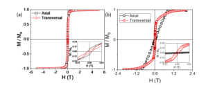
Figure 1. RT - Hysteresis loops in axial and transversal geometries of the linear system (a) and of the helical system (b).
The hysteresis loops in the two geometries overlap in the case of the linear micro-system. In order to explain these features, we recall micromagnetic simulations on cylindrical soft magnetic nanowires (with diameter of 100 nm) of high aspect ratio [1]. Considering that the simulations indicate a coherent magnetization reversal in transversal geometry and a magnetization reversal through movement of domain walls in axial geometry we conclude that the similar shapes of the hysteresis loops in the two geometries is due to the superposition of the two magnetization reversal mechanisms. The much gradual magnetization reversal in axial geometry observed in the case of the micro-coil system as compared to that of the linear system hints to a progressive rotation of magnetic moments of the helical turns that are antiferromagnetically coupled by magnetic dipolar interactions [2]. The hysteresis loop of the micro-coil system in transversal geometry is more rectangular than that obtained in axial geometry. This behaviour can be explained by considering that the preferred magnetization orientation induced by the shape anisotropy is the direction tangential to the coils. These observations are useful in comparing MR properties of the micro-wire and micro-coil systems.
Figure 2 presents MR curves collected at 150 K and at 300 K in axial and perpendicular geometries of the linear and helical systems.

Figura 2. MR curves collected at 150 K (I) and 300 K (II) in axial (a) and perpendicular (b) geometry.
MR curves of the helical system differs from those of the linear system by the minimum registered at the field removal. This can be explained in the anisotropic magnetoresistance (AMR) framework by considering a preferential magnetization orientation tangential to the helical path of the coil which is perpendicular to the current flow direction.
We investigated the angular dependence of the MR on the external field in the case of the micro-coil system. Starting with the field applied perpendicular to the long axis of the coil the sample was rotated yielding resistance vs. rotation angle curves. Figure 3 illustrates the curves registered with different filed strengths. The shape of the curves is specific to AMR characteristics with sin2 dependence as the external field is strong enough to force magnetization along its direction.
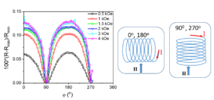
Figura 3. RT - Angular dependences of MR at different values of the external field
The discovery of the optical effect magneto-chiral anisotropy based on symmetry arguments raised the question if the same symmetry arguments can lead to new magneto-transport/MR effects in chiral conductors. In [3] the electrical resistance of a chiral conductor subjected to a magnetic field contains a term ( is the electrical current and is the external magnetic field; is a factor that ensures parity reversal symmetry: ). This term was associated to the electrical magnetochiral anisotropy.
An electrical conductor is chiral if it is composed of a material that crystallizes in a chiral space group, if it contains chiral subunits (e.g. DNA molecules) or if it is shaped into a helical structure. Scattering on chiral molecules can be modelled at a larger scale of a microhelix [3]. MR effects of helical systems are determined by electron scattering on specific magnetic configurations related to curvature-induced anisotropy. MR effects specific to helical systems make them suitable for applications such as tubular magneto-resistive devices [4].
We studied further the chirality of the current in axial geometry as the difference between the MR effect obtained with different current polarities. We found a linear MR at fields lower than the saturatioin field (Figure 4). Thus we confirmed the previous results presented in [3].
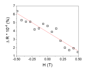
Figure 4. Magneto-chiral resistance obtained with opposite current polarities.
We investigated the magneto-chiral anisotropy in helical systems of opposite chirality at RT (Figure 5).
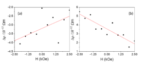
Figure 5. Magneto-chiral resistance in helical systems of opposite chirality D (a) and L (b).
Slopes of different sign obtained in the case of magneto-chiral resistance of helical systems with opposite chirality can be explained by the self-field induced in the coil which is of different orientation at opposite coil chirality.
The magneto-chiral resistance was evidenced by the relative difference between MR curves registered on systems of opposite chirality. Figure 6 presents the relative difference beween MR curves registered on systems of opposite chirality at 150 K and 300 K with different current polarization.

Figure 6. Relative variations of magneto-chiral resistance registered at 150 K (I) and 300 K (II) with different current polarization (a)/(b).
The electrical resistance of a coil depends on several parameters: current intensity, applied field, self-field, temperature. At low temperatures (150 K) linear relative variations of the magneto-chiral resistance vs. applied field were obtained. With increasing temperature the superparamagnetic entities present in the material become more and more oriented in the direction of the applied field. Irrespective of temperature and current polarization, the relative variations of resisitvity in the case of systems with opposite chirality increase linearly from a field corresponding to the shape anisotropy up to the field removal. This behavior can be explained considering the self-field induced in the coil - with opposite orientations for opposite coil chirality - which is predominant at the field removal.
For an indirect control of the spin structure of the helical system via trapped field in superconductors we prepared a helical system with a cylindrical superconducting core. The helical system was made of a Kanthal wire with 200 mm diameter and it is composed of 15 turns. The wire was covered with an electrical insulating varnish. The diameter of the helical system is 4.3 mm (Figure 7 (a)). The superconducting core is a MgB2 bulk with diameter of 4 mm and length of 8.5 mm.
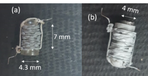
Figura 7. Helical system made of a Kanthal wire (a) Helical system with a superconducting core (b)
The similar shape of the MR curves registered at temperatures crossing the critical temperature of the superconductor (TC) (Figure 8) is due to the low intensity of the traped field. The shape of the MR curves can be explained in the AMR framework.

Figure 8. MR curves registered at 15 K (a) and 50 K (b) on the helical system with superconducting core
In order to acheive an indirect control of the spin strucure of a ferromagnetic layer by means of trapped field in superconductors we prepared systems of superconductor/insulating layer/magnetic layer heterojonctions. We used bulk superconductors that were studied in the previous project implementation stage. The prepared samples are presented in Table 1.
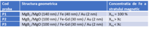
Table 1. Sample codes, Geometrical structure and Fe concentration of the magnetic layer.
All samples were covered with an Au layer in order to prevent oxidation of the metallic layers.
The Fe concentration varies in samples P2 and P3 around the magnetization compensation point (Xc = 77 % Fe).
The magnetic properties of P1-P3 systems were investigated by SQUID (Superconducting Quantum Interference Device) magnetometry. Zero-field cooled – field cooled (ZFC-FC) curves and the hysteresis loops collected at different temperature values in the range 20 K – 45 K are on these samples are presented in Figures 9-11. The thermomagnetic curves were registered by cooling the sample from a temperature higher than TC in the field absence. Subsequently, a 100 Oe field was applied and the thermomagnetic curves were recorded. ZFC-FC curves show a tranzition from superconducting to normal state at 37.5 K for all samples.

Figure 9. ZFC-FC curve (a) and hysteresis loops recorded at 20 K(b), 35 K (c) and 45 K (d) on P1 sample.

Figure 10. ZFC-FC curve (a) and hysteresis loops recorded at 20 K(b), 35 K (c) and 45 K (d) on P2 sample.

Figure 11. ZFC-FC curve (a) and hysteresis loops recorded at 20 K(b), 35 K (c) and 45 K (d) on P3 sample.
Hysteresis loops in perpendicular geometry (field applied perpendicular to the sample plane) were recorded at different temperature values around TC: 20 K, 35K, 45 K. At temperature values lower than TC the hysteresis loops are specific to type II superconductors. Jumps can be observed in the hysteresis loop recorded at 20 K of the P1 sample and this can be explained by thermomagnetic instabilities or by the density of the bulk sample. Asymmetric hysteresis loops with respect to the applied field were obtained at temperatures lower than TC for all samples. Symmetric hysteresis loops are recorded at temperature values close to TC. Hysteresis loops recorded at 45 K in perpendicular geometry with an accentuated unsaturated character indicate the presence of a paramagnetic component or a strong in-plane anisotropy. The hysteresis loop recorded in longitudinal geometry of the P2 sample can be explained by the diamagnetic character of the bulk superconductor (this supposition can be excluded by the shape of the hysteresis loop in perpendicular geometry at the same temperature) or by a magnetic component with out-of-plane anisotropy that is specific to RE-TM thin films [5].
MR curves of P1 sample collected in perpendicular geometry (field applied perpendicular to the sample plane) and in transversal geometry (field applied parallel to the sample plane but perpendicular to current direction) at different temperatures crossing Tc are presented in Figures 12 and 13.
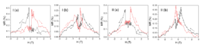
Figure 12. MR curves collected at 15 K (I) and 25 K (II) in perpendicular (a) and transversal (b) geometry.
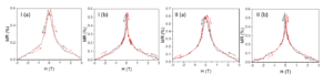
Figure 13. MR curves collected at 37 K (I) and 40 K (II) in perpendicular (a) and transversal (b) geometry.
The shape of the MR curves collected at temperatures below TC cannot be simply explained in the AMR framework. It is necessary to consider that the magnetic moments will reorient under the action of superposed fields: the applied field and the field trapped in the superconductor. Below Tc two maxima are obtained that correspond to the low critical field of the superconductor. Above Tc the observed maxima correspond to the coercive field identified in the magnetic hysteresis loop.
MR curves of P2 and P3 collected in perpendicular geometry at temperatures around TC are presented in Figure 14.
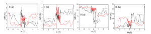
Figure 14. MR curves of P2 (I) and P3 (II) collected in perpendicular geometry at 15 K (a) and 45 K (b).
In order to explain the MR curves of P2 and P3 we investigated their structural, magnetic interactions and magneto-transport properties. X-Ray Diffractograms of P1-P3 are presented in Figure 15. The formation of an Fe bcc phase is observed in the case of P1 sample whereas Fe or Gd phases could not be identified in the case of P2 and P3. MgB2, MgB4 and MgO crystalline phases of the bulk superconductor substrate were evidenced.

Figure 15. X-Ray Diffractograms of P1 (a), P2 (b) and P3 (c).
Room temperature Conversion Electron Mossbauer (CEM) Spectra collected of P1-P3 samples are illustrated in Figure 16. CEM spectrum of P1 was fitted with two hyperfine fied distributions centered on high and low field regions. The two distributions were associated to different local atomic configurations of Fe. The distribution presenting a maximum at 33.3 T is specific to bcc Fe. The low field distribution is specific to Fe nuclei in fcc phase (Fe nuclei with Au neighbors in fcc matrix). The same phase of Fe nuclei with Au fcc surrounding is identified in the case of P2 and P3.
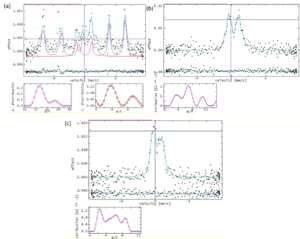
Figure 16. RT CEM spectra of P1 (a), P2(b) and P3 (c).
The MOKE (Magneto-Optical Kerr Effect) loops of P1-P3 samples are presented in Figure 17. A soft magnetic Fe phase is identified in the case of P1. The low signal of the MOKE loops collected on P2 and P3 indicates the formation of paramagnetic phases at room temperature.
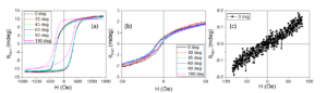
Figure 17. MOKE loops of P1 (a), P2 (b) and P3 (c).
The resistivity vs. temperature curves of P1 and P2 are presented in Figure 18. The resistivity decrease with temperature is specific to oxide phases.

Figure 18. Resistivity vs. temperature dependences of P1 (a) and P2 (b) registered in the absence of filed.
We repeated the preparation of a superconductor/insulator/magnetic layer heterojonction presented in the previous stage of the project. The thickness of the insulating MgO layer was 100 nm and the thickness of the Fe magnetic layer was 40 nm. This sample is denoted in the following S_Fe. It was characterized in comparison with a reference sample with an identical design, but prepared on oxidized Si substrate from magneto-transport point of view. Rezistivity vs. temperature dependences of S_Fe sample and of the reference sample are presented in Figure 19.
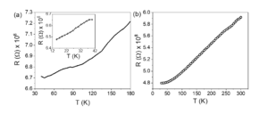
Figure 19. Resistivity vs. temperature dependence collected in 0.1 T field on S_Fe; Resistivity vs. temperature dependence collected in the absence of field on the same sample (a). Resistivity vs. temperature dependence collected in the absence of field on the reference sample (b).
Resistivity vs. temperature dependences confirm the metallic character of the heterojunction and of the reference sample.
MR curves of S_Fe collected in perpendicular geometry at 15K with different applied current intensity are shown in figure 20. The magnitude of MR effect is around 10%. The shape of MR curves cannot be simply explained in the AMR framework according to which the resistance depends on the relative orientation of the magnetization with respect to the current direction. Below TC, Fe magnetic moments will reorient under the superposed influence of the applied field and of the remanent magnetic flux in the superconducting layer. The shape of the MR curves can be related to the base superconductor’s hysteresis cycles. Minima in MR curves correspond to values of applied magnetic field related to maxima in the hysteresis loop. MR curves show no only an inverse evolution with respect to the applied field, but also an MR effect which is more than one order of magnitude higher in the superconducting state of MgB2. These features can be explained in the AMR framework taking into account that the orientation of the magnetic moments is influenced not only by the applied field but also by the distribution of the trapped field in the superconductor at temperatures below TC which competes with the intrinsic in plane anisotropy of the magnetic layer.
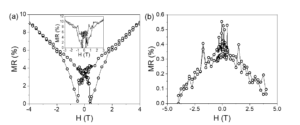
Figure 20. MR curve of S1_Fe collected at 15 K with a current of 0.06 mA (a); MR curve of S1_Fe collected at 15 K with a current of 0.03 mA (inset); MR curve of S1_Fe collected at 40 K with a current of 0.06 mA (b).
The MR curve collected at 40 K for the S1_Fe sample shows a different shape from those obtained at temperatures below TC. The shape is specific to the reorientation of the magnetic moments under the action of the applied field. The resistance increases with decreasing the strength of the applied field as the magnetization change orientation from a perpendicular direction to the current flow to the easy axis of magnetization when the magnetic field is removed.

Figure 21. MR curves of the reference sample collected at 30K with a 0.02 mA current (a). MR curve of the referece sample collected at 300K with a 0.02 mA current (b).
Figure 21 shows MR curves of reference sample collected at 30 K and 300K. The shape of the MR curve at 30K for the reference sample is different from the one registered on the heterojunction below TC. The MR curves of the reference sample collected at 30K and 300K can be explained in the AMR framework.
References:
[1] A. Kuncser, S. Antohe, V. Kuncser (2017). A general perspective on the magnetization reversal in cylindrical soft magnetic nanowires with dominant shape anisotropy. Journal of Magnetism and Magnetic Materials, 423, 34-38.
[2] L.C. Sampaio, E.H. Sinnecker, G.R.C. Cernicchiaro, M. Knobel, M. Vázquez, J. Velázquez (2000). Magnetic microwires as macrospins in a long-range dipole-dipole interaction. Physical Review B, 61(13), 8976.
[3] G.L.J.A. Rikken, J. Fölling, P. Wyder (2001). Electrical magnetochiral anisotropy. Physical review letters, 87(23), 236602.
[4] Maurenbrecher, Henrik, et al. "Chiral anisotropic magnetoresistance of ferromagnetic helices." Applied Physics Letters 112.24 (2018): 242401.
[5] A. E. Stanciu, et al. (2020). Unexpected magneto-functionalities of amorphous Fe-Gd thin films crossing the magnetization compensation point. Journal of Magnetism and Magnetic Materials, 498, 166173.
C. Locovei, N. Iacob, G. Schinteie, A. E. Stanciu, A. Leca, V. Kuncser, "Tuning the magnetic properties of amorphous Fe-Gd thin films by variation of thickness and composition." Hyperfine Interactions 242.1 (2021): 1-12; https://doi.org/10.1007/s10751-021-01763-1
G. Greculeasa, A. E. Stanciu, A. Leca, A. Kuncser, L. Hrib, C. Chirila, I. Pasuk, V. Kuncser, Influence of Thickness on the Magnetic and Magnetotransport Properties of Epitaxial La0. 7Sr0. 3MnO3 Films Deposited on STO (0 0 1). Nanomaterials, 2021, 11(12), 3389.
Locovei, N. Iacob, G. Schinteie, A.E. Stanciu, A. Leca, V. Kuncser, Tuning the magnetic properties of amorphous Fe-Gd thin films by variation of thickness and composition. Hyperfine Interactions, 2021, 242(1), 1-12.
C. Locovei, C. Radu, A. Kuncser, N. Iacob, G. Schinteie, A. Stanciu, A. Leca, V. Kuncser, Relationship between the Formation of Magnetic Clusters and Hexagonal Phase of Gold Matrix in AuxFe1− x Nanophase Thin Films. Nanomaterials, 2022, 12(7), 1176.
A.E. Stanciu, G. Schinteie, A.C. Kuncser, C. Locovei, L. Trupina, N. Iacob, A. Leca, B. Borca, V. Kuncser, Magnetic Properties of Nanosized Fe and FeCo Systems on Trenched Mo Templates. Coatings, 2022, 12(9), 1366.
PROJECTS/
Copyright © 2026 National Institute of Materials Physics. All Rights Reserved